Wednesday, May 13, 2009

XM Radio Mod / Hack - Pioneer GEX-FM903XM

This is the mod /hack for the Pioneer GEX-FM903XM tuner.

Open the case with the 4 screws.
Remove the screw for the heat sink for the Voltage Regulator transistors.
Remove the screw in the center of the board.
Twist the metal pieces along the edge of the board that are used as hold downs.


You can tap the audio in 2 different places.

#1. Tap near the 8pin IC near the center of the board, on the top.
There are 2 surface mount resistors, one above and one below the IC. They are both Grey in color . Tap the left side of each.


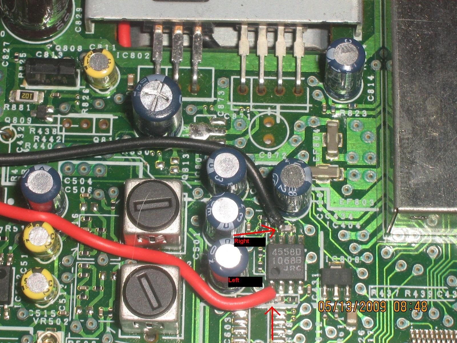
This will give you your Left and Right channel + audio.
You can get ground - from one of many place. You can use the center screw in the middle of the board, or one of the metal lids over the DIGITAL or ANTENNA modules.


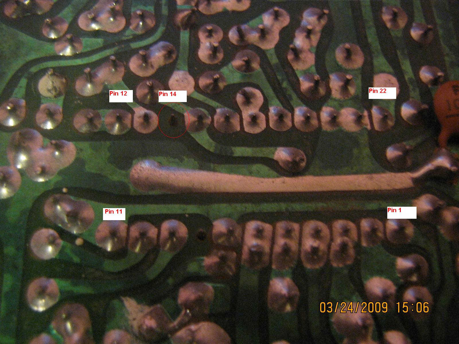
#2 spot is on the bottom of the board.
There are some test points on the top left of the board.
Locate the 3 test points labeled:
RCH AGND LCH


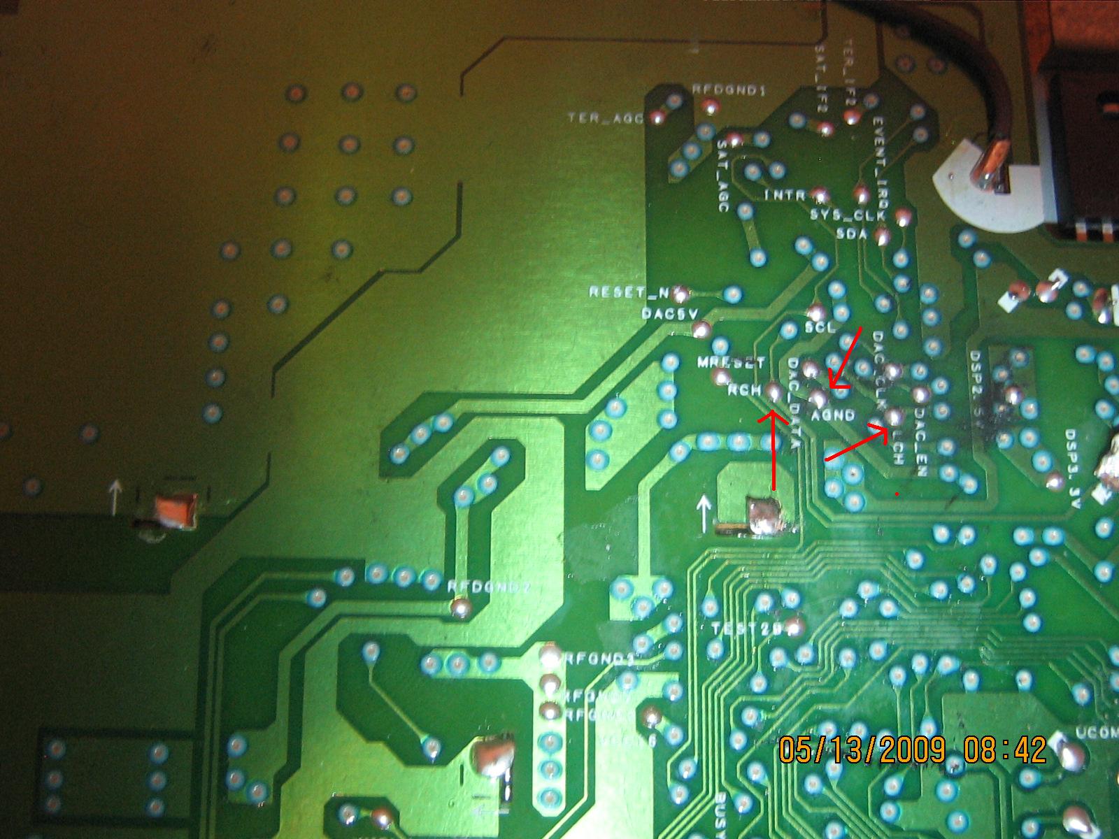
These are the Right Channel, Audio Ground and Left Channel.
Simply tap all 3 of these for audio.


That is all there is to it, for getting RCA audio out of the Pioneer GEX FM 903 XM tuner.

Labels: , , , ,

Wednesday, March 25, 2009

RX Recieve boost on Cobra 29 and Uniden PC 78

Here is a very simple was to use 1 or 2 components to add super recieve boost to a Cobra 29 or Uniden PC78 CB radio.

Parts + tools required:
CB radio (duh)
Soldering pencil 15-40w. Do NOT use a large gun.
Small solder like .032" 60/40 mix or similar mix.
22-24guage wire
220k to 470k ohm 1/4 or 1/2watt resistor.
Simple SPST switch or existing switch on radio.

Disconect the power cord from the radio. Dont do any work with it plugged in, just in case.

1st find pin 14 on the PLL of the radio. Do this with the radio upside down, front facing you.
you will see that Pin 14 is a blank pin with no traces, or it may have a small capacitor on it going to the large ground trace.
Solder a wire to that, being very carefully not to use too much heat or leave it on too long, as the PLL chip is very fragile.
Attach this wire to your switch with about 4-8" of wire, depending where your switch is located. If using an existing switch read below. I prefer to use the pointless CH9 switch.

On the other side of the switch connect your resistor. Be sure to trim the resistor so it doesnt have a long leg to where it may touch anything else.
On the other side of the resistor, add about 6-8" of wire.

Now find Resistor R11. You will need to tap the wire onto this resistor on the end of the resistor closest to the BACK of the radio. If you test it, you should get about + 0.8volts from here. This is going to supply the power for you receive boost.

Thats it! 2 wires, a switch and a resistor.
The reason you need a switch is cause this is going to be VERY sensitive and you should only use it when you need it, cause strong signals may peg your meter.
I got results of a signal of 2db with the boost off. I flipped it on and it jumped to 10+db.
This doesnt just increase the meter reading. It boosts up the actual receive and makes it so much louder and clearer.

I recomend using the 470k ohm resistor as the 220k may be too high, and the 470k is plenty for any of my customer's needs.

This should work on all the Cobra 29 models.
Cobra 29 WX
Cobra 29 LTD
Cobra 29 Classic
Cobra 29 ST
or any other variation, Except the older D858 PLL chip.
It also works for the Uniden PC 78 models or any variation.

Labels: , , , , , , ,