Tuesday, June 23, 2009

Convert Computer Power Supply to use for CB / Ham radio

Got a old computer or power supply laying around?
Put it to good use, by converting it to a 12 volt supply for a CB or small ham radio.

1st of all, most power supplies cant just be wired to work for 12 volts, the right way.
Im using an older power supply, not sure what the type is (sorry) but it used a push button hard on/off switch on the computer.

**Make sure the power cord is disconnected**
Take the power supply apart.
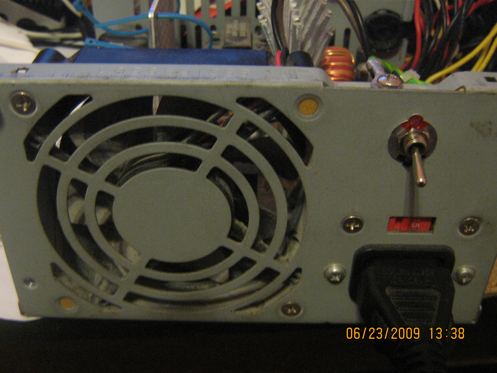
I removed the old push button on/off switch and re-wired it to a SPST 6a/125v toggle switch.
I drilled it into the case, above the power cord location. This allows me to have a self contained switch, instead of one hanging on a cord.


Yellow wires are going to be you +12volt.
Black wired are Neg.
Red wires are +5 volt.
White wire is -5volt
Blue wire is -12 volt.

Remove the Blue, White and all but 1 red wire. Just cut them as close to the pins as possible.
You will need 1 red wire.
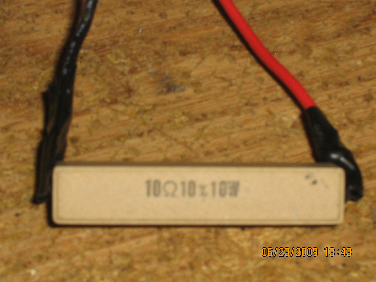
You will also need a 10 ohm, 10 watt resistor, available from Radio shack.
This will need to be wired and soldered inline with a Black Negative wire, to put a load on the +5volt circuit. Without this, your power supply wont produce the correct voltage.

Without a load on the +5volt circuit, I tested 10.2 volts on the 12volt wires. After adding the load resistor, I got 12.1 volts.
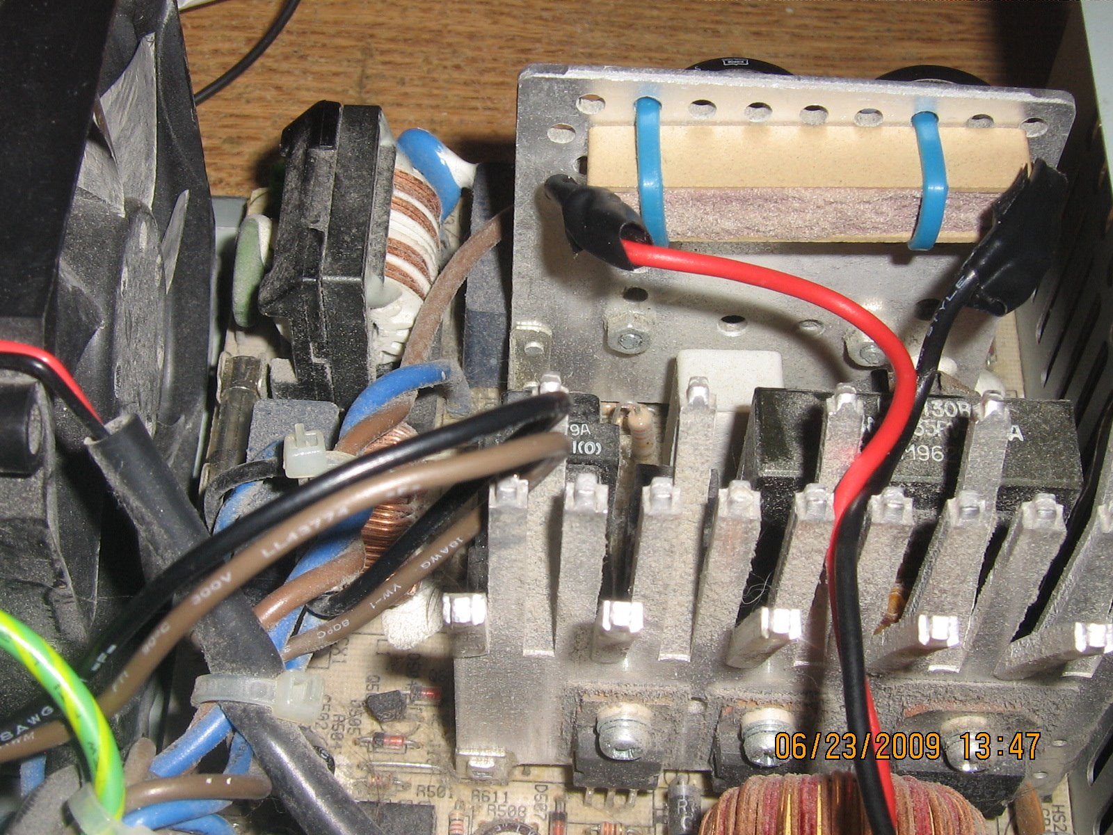
You will need to secure the resistor to a heat sink or to the case, with zip ties, because this will need some metal to cool it, as it will get hot. You can put it near the fan too, to keep it cooler.


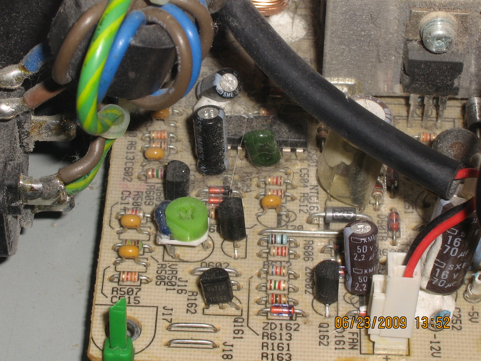
I also found the voltage regulator VR pot, and I adjusted it to the max, which gave me 12.5volts, which makes it even better for 12 volt equipment.


Now all you need to do is limit the amount of +12voltwires and Negitivewires that you will need, as there are probably more than you will ever need. I cust all but 4 of each.

Now put the power supply back together, and thats it!
Now I have a 12 volt, 7 amp power supply for under $5 in parts.

Labels: , , ,

Tuesday, June 9, 2009

Cobra 25, 29 Uniden PC 66, 68, 78 Talkback Mod

This is a easy $1 mod to add talkback to your CB Radio.
This will work for the following radios with no problems.

Cobra 25
Cobra29
Uniden 66
Uniden 68
Uniden 76
Uniden 78
and many more.

All you need is a simple resistor added to the bottom of the board, near the Ext and Pa speaker jacks.

Find the 2 solder points, closest to the rear of the radio, directly above the EXT and Pa jacks.
These are going to be the Negative or Ground side for the audio.

Solder a 1/4 or 1/2 watt resistor between these two solder points. Make sure that the resistor itself does not short out anything on the board or touch anything else. You can wrap it in tape, heat shrink or just keep it lifted slightly above the board.


Use a 100-500 ohm resistor.
The Lower the resistance is, the Louder it will be.
A 100 ohm will be Louder than a 470 ohm.
I like to use a 220 for most mics, or a 470 for good power mics.
You can also wire up a 1K variable pot to adjust the volume level.
You can also use a switch to turn it on/off, just wire it in series.
Ive used the Norm/Ch9/Ch19 switch as a Off/Low/Hi with 2 resistors, to make it adjustable for different mics or volume levels.


Thats it! Just 2 solder points for basic talkback.

Labels: , , , , , ,

Monday, June 8, 2009

CB Mic Connector Problem

If you have ever had a CB mic that randomly cuts out on the Receive, Transmit or Audio, even when you have checked the wiring in the plug and it seems fine, then this is the EASY fix for most radios.

Most radios, including Cobra, Uniden, Galaxy and more use a connector that can fail easily, but its a simple 30 second FREE fix.
This is only for 4 pin microphone connectors, as the 5 and 6 pin are built different.

If you look closely at the male pins on the radio's connector, you will notice that they are split down the center. I have found over the years that these pins tend to get pinched together and flattened, when they should be slightly spaced apart, to create a good electrical connection.


Simply take a small flat head screwdriver and push it into the slots on the pins and spread them SLIGHTLY apart. Spread them less than 1mm. If you spread them too much, you can bend they way out of place and they may break when trying to bend it back.
This allows the MALE pins to fit better into the FEMALE holes in the mic's plug.

this should solve most problems, as long as the wires are soldered properly.
I have done this in over 50 radios over the years after other people have tried to re-wire mic plugs and swap out mics endlessly, when it was just a simple bad connection thats easily overlooked.

Labels: , , , , ,

Wednesday, May 13, 2009

Sirius Sat Radio Antenna Hack / Mod

Sirius XACT XTR3 Tuner.

This will mod improve the FM radio signal on your unit.
Open the unit up by removing the 2 screws on the bottom, using a Hex screwdriver.
Remove the top cover.

The large copper wire circle is the FM broadcast antenna that sends the signal to your radio.


There are 2 ways to improve your signal.

#1. Find the top part of the loop wire, and CUT it at the connection point to the board. Cut it in 2 places, about 1mm apart, so that it cant touch anymore. This goes back to ground and decreases the range.


#2. Do the #1 mod, but also solder a 31" piece of thin wire (24-18gauge) to the BOTTOM connection point.


This will now be a full length wire antenna.
This wire will be tuned to the 89 MHZ portion of the radio band, which is where most Sat Radios are tuned to, due to empty radio stations in that range.
Try to keep the wire straight, and not bunched or coiled up.

Radio Shack HTX-242 COS / COR Mod

This is a mod for the Radio Shack HTX 242 radio.


It allows this 2 Meter Ham Radio mobile to allow COS /COR sense to be used for a repeater RX or other use requiring squelch or signal sense.

Open the bottom cover on the radio by removing the 4 screws.


On the radio's front right, find the 3 transistors about 1 inch in from both the front and right side.
There is a resistor with a "473" printed on it, just below the top transistor. Tap off the RIGHT side of this resistor.


This will provide ~ +3VDC when no signal is present, and will drop to 0v when there is a signal.
This is a High to Low signal point. Most repeater controllers can be switched to select the correct setting. If not, you can make a small signal transistor switching circuit.

XM Radio Mod / Hack - Pioneer GEX-FM903XM

This is the mod /hack for the Pioneer GEX-FM903XM tuner.

Open the case with the 4 screws.
Remove the screw for the heat sink for the Voltage Regulator transistors.
Remove the screw in the center of the board.
Twist the metal pieces along the edge of the board that are used as hold downs.


You can tap the audio in 2 different places.

#1. Tap near the 8pin IC near the center of the board, on the top.
There are 2 surface mount resistors, one above and one below the IC. They are both Grey in color . Tap the left side of each.


This will give you your Left and Right channel + audio.
You can get ground - from one of many place. You can use the center screw in the middle of the board, or one of the metal lids over the DIGITAL or ANTENNA modules.


#2 spot is on the bottom of the board.
There are some test points on the top left of the board.
Locate the 3 test points labeled:
RCH AGND LCH


These are the Right Channel, Audio Ground and Left Channel.
Simply tap all 3 of these for audio.


That is all there is to it, for getting RCA audio out of the Pioneer GEX FM 903 XM tuner.

Labels: , , , ,

Tuesday, May 5, 2009

Selectone ST-907 Programmer Board

I had a request by E-Mail to help a fellow HAM operator get info or a schematic on the no longer supported Selecton Model ST-907 programmer board for DTMF and ANI Tone Encoder boards. Selectone no longer has any info on it, so I made up a schematic.


Parts List, From Left to Right.
36 Pin Parallel Printer Connector
9v Battery Clip
13 Pin programming connector for Selectone boards
Zenier Diode
10K 5% 1/4w Resistor
100K 5% 1/4w Resistor
Zenier Diode
47K 5% 1/4w Resistor
2N4401 Transistor
47K 5% 1/4w Resistor
10K 5% 1/4w Resistor
2N3906 Transistor
10K 5% 1/4w Resistor


All the pins #19-36 are connected to ground/neg.
12 holes are provided on the bottom of board for prototyping, testing or direct wiring.

My schematic isnt 100% exactly the same on the trace locations, and its not to scale, but the original board used a double sided traces, so I had to modify it a little bit for one sided viewing, so it wouldnt get confused, as some traces were too close or overlapped on top and bottom. I did try to get it as close as possible tho.


Software for the ST-907 board can still be found on the Selectone website.
http://www.com-spec.com/selectone/download/st_confg.zip


I made the schematic using a cool program called ExpressSCH. You can built schematics and have a company make PCB boards for you for a reasonable price, if you wish.
The software can be found below for FREE!
http://www.expresspcb.com/ExpressPCBHtm/Free_schematic_software.htm

Here is my file for the Selectone ST-907 Board.
http://www.mark-rodgers.com/Project%20Pics/Selectone%20ST-907.sch

Please let me know if you have trouble downloading the file.

Labels: , , ,